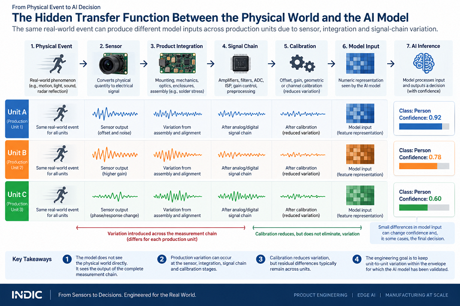
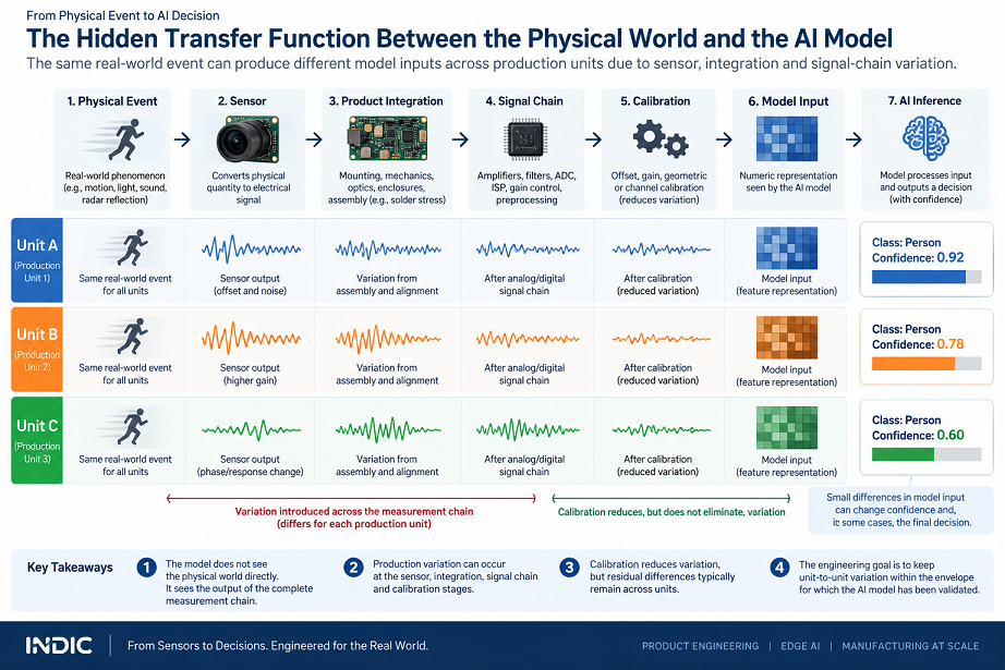
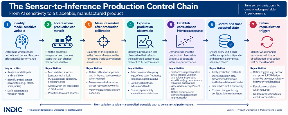
The control chain changes the manufacturing question from “does the sensor work?” to “does this serialized product produce measurement behavior that remains inside the envelope the intelligent function was validated against?”
Calibration is one production control, not the whole strategy
Calibration is often the first response to unit-to-unit sensor variation, but it is only appropriate when the error can be measured and corrected with a stable model. Offset and scale errors may be good candidates. Geometric misalignment, acoustic or optical path changes, nonlinear effects, temperature dependence or unstable mechanical coupling may require different controls.
Timing also matters. Bosch's accelerometer guidance recommends calibration after assembly because soldering and PCB bending can move offset. ST's VL53L4CD manufacturing flow likewise places offset—and, when cover glass is used, crosstalk—calibration in the customer manufacturing process. These examples support a narrower design rule: where calibration is intended to compensate variation introduced by an assembly or integration step, it generally needs to occur after that step—or the calibration architecture must explicitly account for the later change.
The next question is residual error. A calibration routine returning “success” is not the product requirement. The team needs to know how much variation remains after calibration, whether that residual is stable across relevant conditions, and whether the model was validated across that residual distribution.
Important boundary: calibration can reduce physical variation, but it does not prove model robustness. The OEM still needs evidence that the residual measurement distribution is compatible with the application-level inference requirement.
Composite engineering scenario: a MEMS motion classifier that passes basic test
Composite engineering scenario — not an Indic customer case
Industrial motion monitor with a three-axis accelerometer
Consider a compact industrial monitor that uses a three-axis MEMS accelerometer and an embedded classifier to distinguish operating states from orientation and motion features. Development units are carefully assembled, calibrated and used to generate training and validation data.
During pilot production, every unit boots, communicates with the sensor and passes basic electrical checks. Under the same controlled fixture stimulus, however, a subset of assembled units produces shifted axis bias and slightly different derived feature values. The classifier still runs; the inconsistency appears as changed confidence and classification margin rather than a hardware fault.
A model-first debug path would immediately question the network. A better diagnostic sequence moves upstream. The team applies known orientations and motion stimuli to multiple assembled units, compares raw axis values, post-calibration residuals and the intermediate features consumed by the model, and identifies the first stage where the population diverges.
Suppose that analysis shows the model is tolerant to most device-to-device noise but is more sensitive to residual post-assembly bias and axis alignment. The manufacturing response can then be targeted: calibrate after final mechanical assembly, use a controlled orientation fixture, add a feature-level functional check, and store the calibration/test result against the unit serial. No arbitrary tighter component tolerance is required if the production observable remains correlated with the model requirement.
The scenario illustrates the handoff: AI validation identifies the sensitive behavior; NPI, fixture, calibration and production-test engineering turn that behavior into a scalable control.
Production test does not always need to rerun the full AI validation suite
A common mistake is to assume that if AI behavior matters, every manufactured unit must execute a complete application-level inference validation. That may be justified for some products, especially where regulation, safety or the application requirement demands it. It is not automatically the most scalable test architecture.
A more useful question is whether product development can establish a production observable that correlates strongly enough with the AI-sensitive behavior. If a controlled fixture stimulus, calibration residual or intermediate feature can demonstrate that the sensing path remains inside the validated envelope, production may be able to use that observable as the unit-level acceptance test while the full AI validation remains part of design/DVT correlation. That substitution is defensible only when the relationship has been demonstrated across representative hardware/process variation and relevant operating conditions, the stimulus and fixture are repeatable enough for the intended acceptance envelope, and the false-accept/false-reject consequences of the production limit are understood.
The correlation must be demonstrated, not assumed. A convenient proxy that does not predict inference acceptance is simply a cheaper test of the wrong thing. The production test method therefore needs its own measurement-system evidence—fixture/stimulus stability, station-to-station control where multiple stations are used, and change control for test software and limits—at a capability level appropriate to the product-specific acceptance envelope.
The correlation study should also be designed around the failure modes that could invalidate it. That may require stratifying units by lot or assembly condition, repeating measurements, and exercising combinations of temperature, vibration, orientation or other operating factors when those factors can interact with the sensor path. Sample size and statistical confidence should be justified from the expected variation and the consequence of a false accept or false reject—not copied from a universal rule or demonstrated only at room temperature.
Designing access to these observables is partly a DFT problem. Indic's Design for Test capability describes adding test access and diagnostic features during design rather than treating testability as an afterthought. Its NPI scope includes process development and assembly tools/fixture design; its published functional-test and end-of-line test pages cover controlled-input/output verification; and its Technical Expertise page describes in-house test solutioning, automated production testing and MES-linked serial test data. In an Edge AI product, the OEM must still supply the AI-sensitive requirement and prove the correlation; the production-side task is to make that requirement testable at scale.
Traceability has to include the intelligent-product configuration
Sensor-to-inference conformance can depend on more than the PCB serial number. If calibration, preprocessing or the model changes the representation used for acceptance, the serialized product state may need to include those identities as well.
Where these states affect acceptance, the accepted unit configuration may include: serialized hardware + calibration state + firmware/preprocessing version + model/runtime version + production-test recipe/result
Not every product requires every element above, and the exact genealogy is application-specific. The principle is that the evidence required to reproduce an acceptance decision should be retained when that evidence materially affects intelligent-function behavior.
This is where conventional manufacturing traceability becomes valuable to Edge AI productization. Indic's published Production Test & Traceability in EMS article describes versioned test recipes, firmware identity and serial-linked test results. The Edge AI-specific extension is to determine whether calibration identity, preprocessing state or model/runtime version also belongs in that product record.
This proposition is deliberately stronger than “keep good records.” If two units fail differently, engineers need to distinguish a physical sensor population issue from a calibration, firmware, model or test-recipe difference. Without configuration genealogy, those failure domains become unnecessarily entangled.
Sensor substitution and mechanical change become requalification questions
A replacement sensor can be electrically and mechanically compatible yet change noise, offset distribution, filtering, timing or temperature behavior. A housing revision can change alignment or mechanical coupling. A calibration update can change the residual distribution. Firmware preprocessing can change the representation without changing the sensor at all.
The requalification burden should therefore follow the sensor-to-inference path rather than procurement labels alone:
- Compare raw sensor behavior under representative stimuli.
- Compare the post-calibration and post-preprocessing representation.
- Check the model-relevant feature or production observable.
- Run targeted inference validation if that representation moved materially.
- Escalate to broader revalidation when the sensing architecture, model interface or intelligent-function behavior changed substantially.
Indic's Product Lifecycle Management capability includes engineering change management. For an intelligent product, the OEM's AI/system team needs to define which changes affect the validated inference envelope so that lifecycle change control can trigger the appropriate technical evidence rather than treating every substitution as either harmless or a full redesign.
Environmental variation deserves its own validation program and is intentionally not expanded here. Temperature, vibration and humidity can interact with sensor behavior and will be addressed separately in this series; Indic's existing Environmental Stress and Screening capability is adjacent manufacturing/reliability infrastructure, not a substitute for application-specific AI validation.
What should be frozen before PVT?
Before production validation or ramp, the OEM team should be able to answer seven questions:
- Which sensor or derived features materially affect the intelligent-function requirement?
- Which production and assembly variables can move those features?
- What does calibration correct, at what assembly stage, and what residual remains?
- What controlled stimulus and observable can production reproduce?
- What evidence—across representative units/lots, relevant operating or environmental corners, and a level of statistical confidence appropriate to the product risk—shows that the production observable predicts acceptable inference behavior?
- Which hardware, calibration, firmware, preprocessing and model identities must be traceable?
- Which changes invalidate the established correlation and trigger requalification?
If those answers are explicit, sensor variation has become an engineered production parameter. If they are not, the line may be very good at proving electrical functionality while remaining blind to the measurement behavior the AI depends on.
Translating the Control Chain to the Production Line
Where sensor-to-inference conformance must be verified at End-of-Line (EOL),
the production test architecture can apply repeatable physical stimuli to the
fully assembled product while measuring the sensor or feature-level observables
that have been correlated to acceptable inference behavior.
Illustrative EOL implementation:
Controlled Physical Stimulus
(for example, motion / light / thermal input)
➔ Production Calibration, Where Required
➔ Production Observable or Feature Check
➔ Acceptance Result and Configuration Data Logged by Serial Number.
Unlike a synthetic data-injection test, this approach exercises the physical
sensing path after the assembly and integration steps that can introduce
variation. Depending on the product, the station may measure residual offset,
gain, alignment, signal quality or another model-relevant observable; apply
unit-specific calibration coefficients; and verify that the resulting
measurement behavior remains inside the OEM's validated acceptance envelope.
The exact stimulus, calibration method, observable and acceptance limit are
product-specific. They should be derived from the correlation established
during development rather than imposed as generic Edge AI production-test
requirements.
Closing perspective: manufacture the validated measurement envelope
The objective is not to make every sensor output identical. That is neither realistic nor necessary. The objective is to understand which residual differences matter to the intelligent function and then keep the shipped population inside the envelope that was actually validated.
That requires coordination across disciplines. AI and system engineering identify model sensitivity. Product engineering determines how assembly, calibration and configuration can move the relevant variables. NPI and DFT make the requirement accessible to fixtures and test. Production test generates acceptance evidence. Traceability preserves the accepted configuration. Change management protects the correlation after release.
Seen this way, sensor variation is not merely a sensor-specification issue. It is a product-industrialization problem with an AI consequence. That is the bridge OEM teams need to engineer before the product reaches scale.
Sensor-to-Inference Production Readiness Assessment
Use the engineering worksheet to map sensor variation, assess model sensitivity, define calibration architecture, build a production-acceptance matrix and specify requalification triggers before an intelligent sensing product enters ramp.
Request the assessment
Selected engineering references
- Bosch Sensortec — BMA400 accelerometer design guide.
- STMicroelectronics — UM2931, VL53L4CD Ultra Lite Driver user manual and production calibration guidance.