Why Late PCB Test-Point Decisions Slow Down Pilot Builds

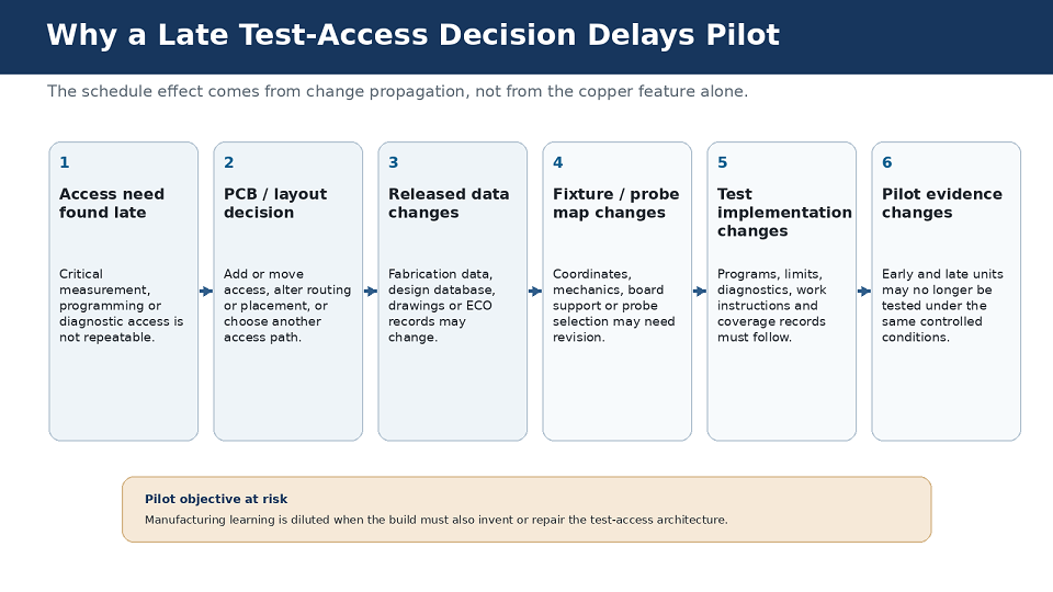
Six-step engineering flow showing a late test-access need leading to a PCB or layout decision, released-data changes, fixture or probe-map changes, test-implementation changes and less directly comparable pilot evidence.

NPI · Design for Testability · Production Test

Why Late PCB Test-Point Decisions Slow Down Pilot Builds

A PCB can be electrically correct and still be unready for pilot if the access needed for repeatable production test and fault isolation has not been closed.

Abstract

Late PCB test-point decisions do more than make testing inconvenient. When required test access is discovered after placement, routing, fabrication release or fixture planning, the resulting decision can propagate through PCB data, fixture coordinates, test software, controlled documentation and pilot revalidation. The build then spends time resolving access dependencies instead of learning whether the manufacturing process is repeatable.

This article focuses specifically on that release-readiness problem: what test access should be defined before pilot, what evidence demonstrates that the access is usable, and how OEM and EMS teams can disposition residual access risk without turning the pilot into a test-development exercise.

Executive Summary

A common assumption is that test points can be finalized after a prototype works. That can be acceptable when the intended manufacturing test and debug strategy already has adequate physical or digital access. It becomes risky when the pilot is the first time the team discovers that a required rail, programming interface, reset condition or communication node cannot be reached repeatably.

This article deliberately addresses a different question from test-coverage sufficiency. The test-coverage article asks what failures must be detected, what evidence is sufficient and which inspection or test method should own that evidence. This article starts after that decision:

Can the released hardware, fixture concept and controlled test infrastructure actually provide the required access before pilot begins?

The release decision is therefore not based on test-point count. It is based on closure evidence: required access is defined, physically feasible, synchronized with the correct PCB and test revision, and any remaining access limitation has an explicit disposition.

Why Do Late Test-Point Decisions Slow Down a Pilot Build?

Because test access is a physical and configuration-dependent design dependency. When the requirement is discovered after PCB and test artifacts have started to harden, a small access change can force coordinated changes across multiple released or partially released items.

A power rail, reset line, programming signal or communication node may look like one schematic requirement. In production, however, the access path has to coexist with component placement, routing, probe approach, board support, fixture mechanics, programming interfaces and the selected test sequence. Once those dependencies exist, moving or adding access is no longer a local edit.

Siemens' DFT guidance recommends moving testability consideration into schematic and PCB design rather than waiting until layout is complete. Cadence likewise notes that in-circuit-test capability has to be designed into PCB layout rather than treated as an activity that begins after the board is finished.

IPC-2231A, DFX Guidelines, provides a broader DFX process framework for printed-board assemblies and includes a dedicated Testability section covering concept design, detailed design, design release and DFT assessment. It does not prescribe the four-gate method used in this article, but its structure reinforces the underlying principle: testability is a design-review concern that should mature with the product rather than being deferred until production.

A Pilot Build Should Produce Manufacturing Evidence, Not Invent the Test Architecture

A pilot build is useful because it exposes the interaction between the released design and the intended production system: material, assembly process, programming, inspection, test, handling, documentation and operator execution. It is a controlled opportunity to learn what is repeatable before ramp.

That learning becomes harder to interpret when the test-access method changes during the same build. If one unit is checked through a manual probe, another through a temporary connector, and later units after a PCB or fixture change, the resulting failure history contains two variables: manufacturing variation and test-system variation.

Engineers can still learn from such a build, but attribution becomes harder. A failure may have changed because the manufacturing process changed, because the product revision changed, because the test method changed, or because all three changed together.

This is consistent with Indic's broader guidance on EMS transfer readiness before pilot. That discussion treats test readiness as one part of the complete transfer package. The scope here is narrower: closing the access dependencies that could otherwise consume the pilot itself.
Six-step engineering flow showing a late test-access need leading to a PCB or layout decision, released-data changes, fixture or probe-map changes, test-implementation changes and less directly comparable pilot evidence.
Figure 1. The schedule effect of a late test-access decision comes from change propagation across coupled design and test artifacts, not from the copper feature alone.

The Real Delay Mechanism Is Change Propagation

Suppose test engineering identifies a node that must be measured or driven during manufacturing. If that requirement is known while placement and routing still have design freedom, the layout team can reserve a valid access path. If it appears after release, the team first has to determine whether to modify the PCB, change the intended test method, use a different exposed feature, add a connector-based path, or accept reduced access.

Late discoveryWhat may have to changeWhat the pilot loses
Critical node has no repeatable access pathPad/via strategy, routing, placement, connector use or test-method allocationTime that should have been spent classifying manufacturing variation
Existing target is mechanically blockedProbe approach, keep-out, fixture mechanics, board support or target locationConfidence that a failed measurement represents the unit rather than the access method
Access location changes after fixture work startsProbe map, fixture CAD/mechanics, verification and revision recordsFixture readiness and station validation move with the design revision
Functional test detects a symptom but cannot isolate itAdditional measurement path, diagnostic sequence, instrumentation or controlled engineering accessRoutine production defects consume engineering debug time
Access method changes midway through pilotPrograms, limits, work instructions, evidence capture and revision controlEarly and late pilot results may no longer be directly comparable

The engineering question is therefore not simply, Can we still add a test point?

It is: Which design, fixture, software and controlled-document artifacts already depend on the current access plan?

Test-Access Decisions Become Harder as the Design Freezes

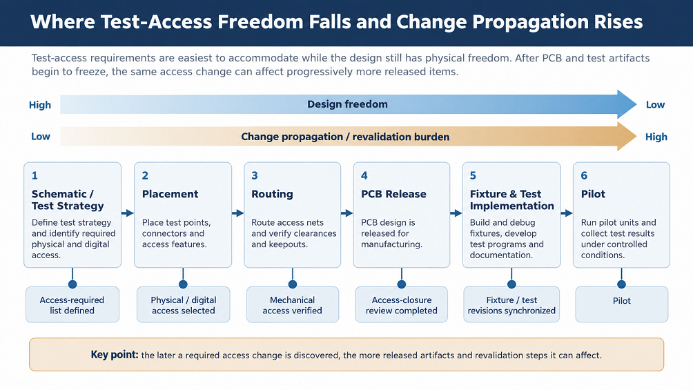
The timing problem is easier to understand if test access is viewed across the design-release sequence rather than as a single PCB-layout activity.

During schematic and early test-strategy work, the team has substantial freedom to decide what needs to be observed, driven or programmed. During placement, there is still flexibility to reserve physical space and choose which side of the board should provide access. During routing, the options begin to narrow. After PCB release and fixture/test implementation, even a small access change can propagate into more artifacts and require more revalidation.

The objective is not to freeze every detail prematurely. It is to close the decisions at the point where keeping them open no longer provides useful design flexibility.

Engineering timeline from schematic and test strategy through placement, routing, PCB release, fixture and test implementation, and pilot, showing design freedom decreasing while the number of affected artifacts and revalidation burden increase.
Figure 2. Test-access requirements are easiest to accommodate while the design still has physical freedom. After PCB and test artifacts begin to freeze, the same access change can affect progressively more released items.

Coverage Defines the Need; Test Access Closes the Design Dependency

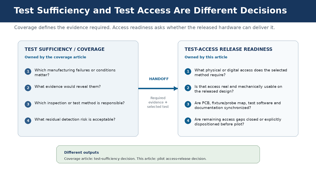
Test coverage and test access are related, but they are different engineering decisions.

Coverage asks which failures matter, what evidence will expose them and which inspection or test method owns that evidence. Access readiness begins once those needs are known.

For this article, the practical question is narrower: What physical or digital path must exist so the selected method can obtain the required evidence on the released design?

Two common test-engineering terms are useful here. Observability means being able to see the electrical or digital evidence of a condition. Controllability means being able to drive, configure or program the circuit sufficiently to expose that condition.

In day-to-day NPI work, those terms translate into a simpler question: What must production measure or drive, and where is the repeatable path that lets it do so?

Two-column diagram distinguishing test-sufficiency decisions from test-access release readiness. The coverage side defines required evidence and test method; the access side verifies physical or digital access, mechanical usability, revision synchronization and closure of remaining gaps.
Figure 3. The coverage decision should hand a defined evidence need and selected test method into the access-readiness review. The two reviews should not be duplicate worksheets.

Can Another Test Method Avoid a Late PCB Change?

Sometimes.

A missing dedicated test point does not automatically justify a respin. The team can first ask whether the required evidence can be obtained through another already controlled access path. That might include an exposed feature suitable for flying probe, an existing connector, a programming/debug interface, supported boundary-scan access or a functional-test stimulus and measurement path.

Method or pathAccess implicationWhen it may avoid a new dedicated pointAccess-specific limitation
In-circuit test (ICT)Usually depends on planned, repeatable fixture contact to selected nodesWhen suitable existing targets are already distributed and mechanically fixtureableAn electrically valid target may still fail fixture-clearance or board-support requirements
Flying probeRequires a reachable exposed feature, but not a dedicated bed-of-nails fixtureWhen the required node can be reached repeatably on low-volume or changing designsProbe approach, component height, geometry and cycle time still matter
Existing digital/programming interfaceUses an already designed connector, header, pad interface or supported digital pathWhen the required state or structural evidence can legitimately be reached through that interfaceIt only solves the objectives the interface actually supports
Functional testOften accesses the product through normal connectors or purpose-built stimulus/measurement pathsWhen the required evidence is inherently functional and the failure can be isolated sufficiently for the pilot objectiveA functional symptom can be too broad if the team still needs local board-level diagnosis

The key question is not whether another method exists in theory. It is whether that method supplies the required evidence with enough repeatability and fault-isolation precision for the pilot objective.

Detailed test-sufficiency and coverage allocation belong in the test-coverage article. This article only asks whether the chosen method has a real, releasable access path.

Weak Test Access Slows Debug Even When the Board Can Still Be Tested

A board may still reach a functional pass/fail decision without ideal structural access. The more subtle issue appears after a failure.

If an industrial controller cannot communicate, the symptom could originate in assembly, connectorization, power, clock or reset behavior, programming state, transceiver circuitry, termination or configuration. Functional test tells the team that the product did not behave as expected. It does not automatically identify which board-level condition caused the failure.

During pilot, engineering debug is expected. The objective is not to eliminate it. The objective is to prevent routine manufacturing faults from consuming the same investigation path as genuinely new engineering problems.

Repeatable access to measurements that discriminate among likely causes can shorten that classification loop even when final production test remains primarily functional.

Representative NPI Scenario: A Working Prototype With No Repeatable Way to Observe a 1.2 V Core Rail

This is an illustrative engineering scenario, not a claimed Indic customer case.

An OEM develops a compact processor-based controller. During prototype debug, engineers monitor a 1.2 V processor core rail by placing a handheld probe on an exposed capacitor pad near the regulator output. That access is adequate on the bench because the engineer can orient the board freely and stabilize the probe by hand.

The prototype passes functional development, and the PCB proceeds toward pilot. The intended manufacturing sequence is still described broadly as programming followed by functional test. No production-access review has established whether the 1.2 V rail needs a repeatable observation point for pilot diagnosis.

During pilot, some units fail to complete the boot sequence.

The functional station confirms the symptom but cannot distinguish among several plausible causes: the core rail may be missing or unstable, reset may not be releasing correctly, the processor may not have been programmed as expected, or another assembly defect may be preventing initialization.

The capacitor pad used on the bench is not a practical production contact. A nearby component restricts the probe approach, the board cannot be supported in the same orientation as it was on the engineering bench, and repeatable manual access would depend heavily on the technician.

At that point the team has several possible responses. It can identify another exposed feature already connected to the same rail, add a dedicated controlled access target in the next PCB revision, modify the fixture or diagnostic process so the rail can be measured repeatably, or determine that another designed interface provides equivalent evidence.

Each option has different consequences. A PCB change affects released board data and may affect any fixture work tied to the original coordinates. A fixture solution affects mechanics and probe mapping. A diagnostic-method change affects test software, work instructions and revision control.

The problem was not that the board lacked a conveniently placed copper pad.

The problem was that a manufacturing evidence requirement—confirm the state of the 1.2 V rail when a unit fails to boot—had never been converted into a repeatable production-access requirement before pilot release.

An access-closure review would not have guaranteed that the pilot would contain no failures. It would have ensured that this particular diagnostic dependency was either designed in, deliberately handled through an alternate method, or explicitly accepted before the build began.

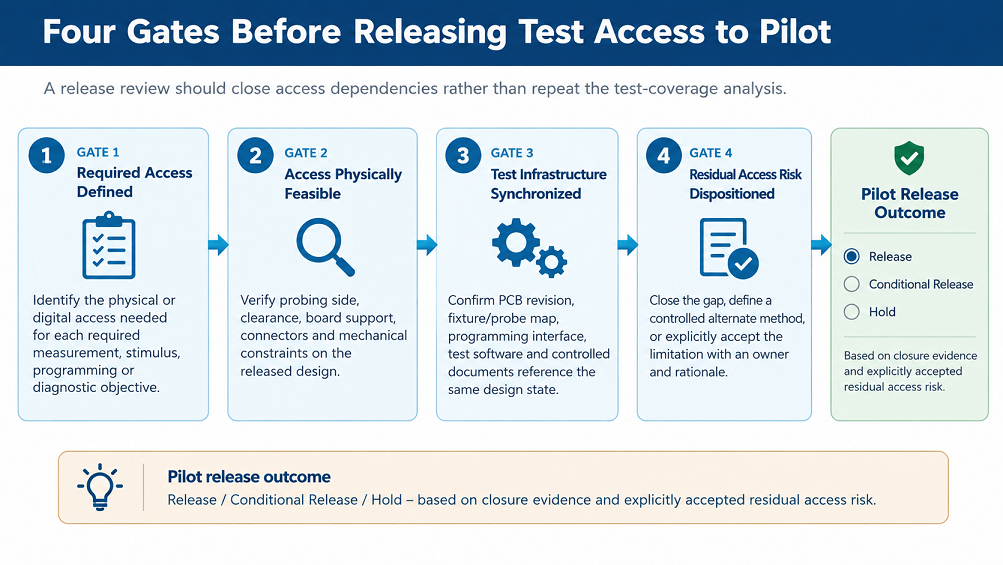
Use a Four-Gate Pre-Pilot Test-Access Release Review

The access review should not repeat the test-coverage methodology.

By the time this review begins, the team should already know which evidence matters and which test method is expected to provide it. The purpose here is to decide whether the design and test infrastructure are ready to support that decision during pilot.

Gate 1 — Required Access Defined

For each required measurement, stimulus, programming or diagnostic objective, identify the physical or digital access path the selected method needs.

The output is an access requirement tied to a function or evidence need, not a generic request for more pads.

A useful requirement is specific enough to survive design review. Record the function or evidence need, required access, current access path, mechanical or layout constraint, and owner.

Function / Evidence Need Required Access Current Access Path Mechanical / Layout Constraint Owner
Confirm 1.2 V core rail during boot-failure diagnosis Repeatable rail-voltage measurement Exposed node or dedicated fixture-access target on the current PCB revision Probe approach and board support must permit repeatable contact Test / hardware engineering
Program and verify MCU image Controlled programming/debug interface Released SWD/JTAG/programming connector or pad interface Interface must remain accessible in the intended fixture orientation Firmware / test engineering

These rows are illustrative. The required evidence and access method must come from the product's actual test strategy.

Gate 2 — Access Physically Feasible

Verify that the required access is real on the current PCB revision and can be used repeatably.

Review probing side, local clearance, tall-component interference, connectors, board support, access concentration and any fixture-specific mechanical constraint.

A target visible in CAD is not automatically a usable production contact.

Gate 3 — Test Infrastructure Synchronized

Confirm that the PCB revision, fixture or probe map, programming-interface definition, test software, controlled work instructions and any access-related documentation reference the same released design state.

In practice, this requires explicit revision linkage rather than relying on filenames or team memory. The PCB release identifier should be traceable to the fixture/probe-map revision and test-program release. Where the organization uses controlled PLM/MES records, design-database or netlist identifiers, checksums, fixture identification or engraving, those identifiers should agree with the released manufacturing package.

A typical pilot synchronization failure is not that the fixture is inherently wrong. It is that the fixture was built against one PCB revision while the board or test software has moved to another.

Gate 4 — Residual Access Risk Dispositioned

Every remaining access limitation needs a disposition before release: close it, define a controlled alternate method, or explicitly accept the residual limitation with an owner and rationale.

The outcome should be Release, Conditional Release or Hold for the access-readiness question.

Four-gate pre-pilot test-access release framework showing Required Access Defined, Access Physically Feasible, Test Infrastructure Synchronized and Residual Access Risk Dispositioned, followed by Release, Conditional Release or Hold.
Figure 4. The four-gate review is a release-readiness method. It begins after the test-sufficiency decision and determines whether the required access can actually support pilot execution.

What Should Be Closed Before Authorizing Pilot?

“Closed” does not mean that pilot can no longer produce engineering changes. Pilot exists partly to generate evidence that drives controlled change.

It means the test-access dependencies are understood well enough that the build can answer its intended manufacturing questions without first discovering how to reach the product.

Access-release itemClosure evidenceRelease implication if still open
Required access pathPhysical or digital path identified for each access-dependent measurement, stimulus, programming or diagnostic objectiveHold or conditional release until an alternate path is controlled
Mechanical feasibilityProbe, fixture or connector access reviewed against current component placement, clearance and board supportElectrical accessibility remains unproven as a production contact
Revision alignmentPCB data, fixture/probe map, interface definition and test software reference the same design statePilot evidence can become difficult to reproduce or compare
Failure-classification pathKnown route for obtaining the measurements needed to distinguish routine manufacturing faults from deeper engineering issuesRoutine defects may fall into open-ended engineering debug
Residual access gapsNamed owner, closure action or explicit risk acceptance with rationaleThe production floor becomes the place where ownership is negotiated

When Should PCB Test Access Be Defined?

The practical answer is not simply “as early as possible.” Different parts of the access decision need to close at different stages.

By schematic and test-strategy review: identify the measurements, stimuli, programming operations and diagnostic objectives that require physical or digital access.

Before placement and routing are frozen: give those requirements an intended access path and determine whether the path is mechanically plausible on the board.

Before PCB and fixture/test implementation are released: complete the access-closure review, verify that the required paths are usable, synchronize the relevant PCB/fixture/test revisions, and disposition any remaining limitation.

These gates are more useful than an arbitrary rule such as “complete DFT when layout is 80% finished,” because programs define layout maturity and release milestones differently.

What Is in the Pre-Pilot Test-Access Closure Register?

The article explains the decision logic. The gated register is intended to make the review executable.

Working fieldPurpose
Function / Evidence NeedDefines the measurement, stimulus, programming or diagnostic objective.
Required Physical or Digital AccessStates what access the selected test method actually needs.
Current Access PathIdentifies the path available on the current PCB/system revision.
Access Available?Records whether the path is usable, conditional or unavailable.
Mechanical or Layout ConstraintCaptures clearance, probing-side, support, connector or placement limitations.
Selected Test MethodRecords which method is expected to use the access path.
PCB RevisionTies the closure evidence to a controlled design state.
Affected PCB / Fixture / Test ArtifactMakes change propagation visible before pilot.
Closure Action or Alternate MethodDefines how an open gap will be closed or controlled.
OwnerAssigns accountability.
Closure EvidenceLinks the release decision to objective evidence or document references.
Pilot Release DispositionRecords Release / Conditional Release / Hold for the item.
Residual Access RiskCaptures the limitation that remains after the selected disposition.
ApproverRecords who accepted the closure or residual risk.
StatusTracks Not Reviewed / Open / In Review / Ready / Accepted Risk / Blocked / N/A.

The purpose is not to assign a universal numerical readiness score. It is to make every important access dependency visible, give it an owner, capture the evidence used to close it, and force unresolved items into an explicit Release / Conditional Release / Hold decision before pilot.

How This Fits With the Rest of the Test Strategy

This article sits between two other engineering decisions rather than duplicating them.

First, the test-coverage sufficiency review determines what manufacturing evidence is required, which inspection or test method should provide it and where residual detection risk remains.

Second, this article determines whether the released PCB and test infrastructure provide the physical or digital access needed to obtain that evidence during pilot.

Indic's existing article on production test and traceability covers the wider relationship among production-test methods and records. Its existing DFT case discussion also illustrates the qualitative consequence of allowing inadequate access to push defect detection downstream.

The next related decision is fixture architecture: how the selected contact and fixture strategy affects debug time, false failures, yield interpretation and throughput. That is a separate engineering problem and should be evaluated after the required evidence and access paths are defined.

Production test and product qualification answer different engineering questions. That distinction is treated in the broader test-coverage and production-test content and is intentionally not repeated here.

Test Access Can Also Affect Later Failure Analysis

The access decision is primarily a production-readiness decision, but some of the same evidence may matter after a product leaves the factory. If manufacturing or service teams cannot obtain the measurements needed to isolate an intermittent fault, a returned unit may require deeper bench or depot-level diagnosis even when the reported symptom is clear.

Closing useful diagnostic access before pilot can therefore support later failure analysis where the same evidence remains relevant. That does not mean production-test access prevents every field escape, nor that every product should expose service-level diagnostic points. The appropriate access depends on the product architecture, service model and risk profile.

FAQ: PCB Test Points and Pilot-Build Readiness

When should PCB test access be defined?

Treat it as three progressively tighter gates. By schematic/test-strategy review, identify which measurements, stimuli, programming operations and diagnostic objectives require access. Before placement/routing freeze, identify and mechanically review the intended physical or digital access path. Before PCB and fixture/test release, close the access review, synchronize the relevant revisions and disposition any remaining gaps.

Does every PCB net need a dedicated test point?

No universal rule requires a dedicated probe target on every net for every product. The access requirement depends on the manufacturing evidence already selected in the test-sufficiency review and on the capabilities and limitations of the selected test methods.

What does “access closed” mean before pilot?

It means the required physical or digital access path has been identified on the current revision, checked for repeatable use, synchronized with the relevant fixture/test implementation, and any remaining limitation has a named disposition and owner.

Can an alternate test method avoid a PCB respin?

Sometimes. An existing connector, flying-probe-accessible feature, supported digital interface or functional measurement path may provide the required evidence. The alternate is valid only if it supplies the required measurement or control with enough repeatability and failure-isolation precision for the pilot objective.

What information should an EMS/test team have before pilot?

At minimum, the team should know which access-dependent measurements or control actions are required, where those access paths exist on the released design, which method uses them, what mechanical constraints apply, which PCB/fixture/test revisions are synchronized, and which access gaps remain conditionally accepted or open.

Closing Perspective

A late test-point request is rarely expensive because the feature itself is complicated. It becomes expensive when the request arrives after PCB layout, fixture planning, test programming and pilot objectives have started to depend on an incomplete access strategy.

The practical discipline is to separate two decisions.

First determine what manufacturing evidence the product needs.

Then, before pilot release, prove that the selected test architecture has a repeatable physical or digital path to obtain it.

Close the access dependencies, synchronize the released artifacts and disposition what remains. That keeps pilot learning focused on manufacturing behavior rather than on repairing the test-access architecture.

Download the Pre-Pilot Test-Access Closure Register

Use the editable register to track required access, current access path, mechanical feasibility, affected PCB/fixture/test artifacts, closure actions, owners, closure evidence, residual access risk and the final Release / Conditional Release / Hold disposition before pilot.

Download the Pre-Pilot Test-Access Closure Register

Selected Technical References

Indic Pre Pilot Test Access Closure Register Fillable
Indic-Pre-Pilot-Test-Access-Closure-Register-Fillable
Close
After signing up the PDF will be emailed to you at the address you provide.  Please use a company address - gmail, yahoo, outlook, etc. will not be accepted.
Thank you! Your submission has been received!
Oops! Something went wrong while submitting the form.
Join us to stay updated with our latest blog updates, manufacturing and assembly trends, news and announcements!
Thank you! Your submission has been received!
Oops! Something went wrong while submitting the form.