Wire & Cable Harness Integration for Complex PCBA and Box Builds
Wire & Cable Harness Integration for Complex PCBA and Box Builds: What OEMs Should Validate Before Production
Why continuity testing a harness and functionally testing a PCBA do not, by themselves, prove that the integrated product is ready for repeatable production.
Abstract
A wire harness can pass continuity. A PCBA can pass functional test. The enclosure can meet its dimensional requirements. Yet the assembled product can still fail during pilot production or later in the field.
The reason is that a harness is not simply another subassembly. In a complex box build, it forms an electrical and mechanical interface between the PCBA, power sources, sensors, actuators, communications, enclosure and other system elements. Routing, connector mating, strain relief, shielding, grounding, assembly sequence and configuration control can therefore affect product behavior even when the harness itself was manufactured correctly.
For OEMs, harness production readiness should be established at three levels: harness integrity, installed integration and system behavior. Each level answers a different engineering question and requires different evidence.
Executive Summary
For relatively simple assemblies, a harness drawing, continuity test and workmanship inspection may provide much of the manufacturing evidence needed at the harness level.
Complex PCBA and box-build products introduce another problem: the harness becomes part of the system architecture once it is installed.
A harness that is electrically correct can still be routed incorrectly, loaded mechanically at a connector, pinched during enclosure closure, installed without the intended service loop, exposed to abrasion, or implemented in a way that changes grounding or shielding behavior. Some of these conditions may not appear during standalone harness testing.
Harness integrity does not establish installed integration, and installed integration does not establish system behavior.
Production readiness should therefore be reviewed at three levels:
Harness integrity — was the harness built correctly?
Installed integration — is it correctly incorporated into the mechanical assembly?
System behavior — does the completed product perform correctly through those interfaces?
The practical consequence is that harness release should be coordinated with PCBA, mechanical, test and box-build readiness rather than treated only as a purchasing or cable-fabrication activity.
A Harness Is a System Interface, Not Just a Cable Assembly
A wire harness performs an obvious electrical function: it connects points within a product.
But once installed, it also occupies physical space, transfers mechanical loads, passes through enclosure boundaries, interfaces with connectors, establishes grounding and shielding paths, constrains assembly sequence and can affect service access.
Consider a harness connecting a PCBA to a motor, sensor, power module or external connector. Its performance depends on more than whether conductor A reaches pin A.
The manufacturing team may also need to know:
Is the correct connector and contact system being used?
Is pin mapping controlled across product variants?
Is the installed bend radius appropriate?
Are wires properly supported as they leave the connector?
Can the harness rub against an enclosure edge?
Is strain transferred into the connector?
Can operators fully mate and verify the connector during assembly?
Are power and sensitive signal paths routed appropriately?
Is shielding terminated as intended?
Can the enclosure close without compressing or displacing the harness?
Can the product be serviced without damaging the harness?
Does production test exercise the interfaces that matter?
The broader lesson for an OEM is straightforward: electrical correctness is necessary, but the installed state matters too.
The Dangerous Assumption: “It Passed Continuity”
Continuity testing answers an important question: Are the intended electrical connections present?
Depending on the test architecture, it may also identify opens, shorts, crossed connections or incorrect pin mapping.
What it cannot establish is equally important. A standalone continuity test normally cannot tell you whether a harness will be pinched when an enclosure closes, whether its routing places unacceptable stress on a connector, whether an intended shield termination has been implemented effectively at system level, whether an operator can reliably seat a connector during production assembly, or whether the completed product behaves correctly under its intended operating load.
A harness can be electrically correct as a manufactured object while still being incorrectly integrated into the product.
The solution is not simply “more testing.” It is determining which failure modes need to be controlled and what evidence can actually expose them.
The Three-Level Harness Integration Evidence Model
Level 1 — Harness Integrity
The first question is: Was the harness itself manufactured correctly?
Depending on product requirements, evidence may include correct wire and cable type; connector and contact identification; pin mapping; termination workmanship; polarity; continuity; labeling; dimensions and branch lengths; sleeving or protection; required electrical insulation testing; and revision identity.
Level 1 establishes whether the harness artifact is correct. It does not establish that the product containing it is correct.
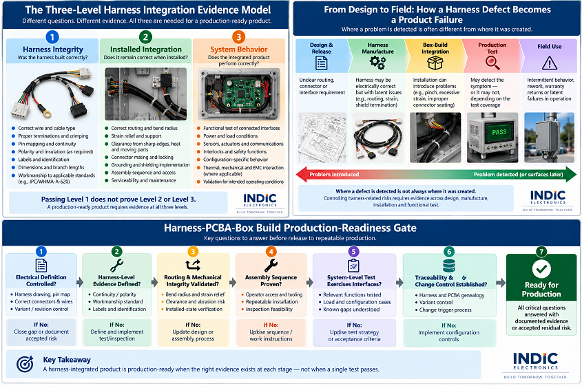
Figure 1. Three levels of harness integration evidence.</strong> Standalone harness inspection and electrical test establish harness integrity; installed-state checks establish mechanical integration; system test provides evidence about the behavior of the completed product. Passing Level 1 does not prove Levels 2 or 3.
Level 2 — Installed Integration
The second question is: Does the correctly manufactured harness remain correctly implemented after installation?
This is where electrical and mechanical engineering meet.
Routing and clearance
A harness must fit within the actual enclosure without unwanted contact with sharp edges, heat sources, moving components, fasteners, covers, busbars or high-voltage conductors, or surfaces that can abrade insulation.
Bend and strain
Routing should not create unwanted loading at connector exits, crimps, splices, transitions or tie-down locations.
Connector access and mating
A connector may be electrically correct but difficult to install reliably. The NPI build should reveal whether an operator can reach it, orient it correctly, fully seat it, engage locking features, inspect the mating condition, and disconnect it during service without damaging adjacent components.
Serviceability
A harness routed efficiently for assembly may still make later service difficult. Service loops, connector access, replacement sequence and identification should therefore be considered when serviceability is a product requirement.
Level 2 answers whether the harness works as installed, rather than merely as manufactured.
Why Assembly Sequence Belongs in Harness Validation
Harness drawings describe the finished configuration. Production, however, must create that configuration through a sequence of operations.
Imagine an enclosure in which one connector becomes inaccessible after a mechanical subassembly is installed. An operator may need to mate the harness first, position the subassembly second and secure the harness third.
Changing the order can create incomplete connector mating, trapped wires, excessive harness tension, rework, damaged connector latches or inconsistent routing.
These problems can be difficult to predict from CAD alone. Pilot builds therefore provide evidence not only about whether the harness fits, but whether the intended configuration can be produced repeatedly through a practical assembly sequence.
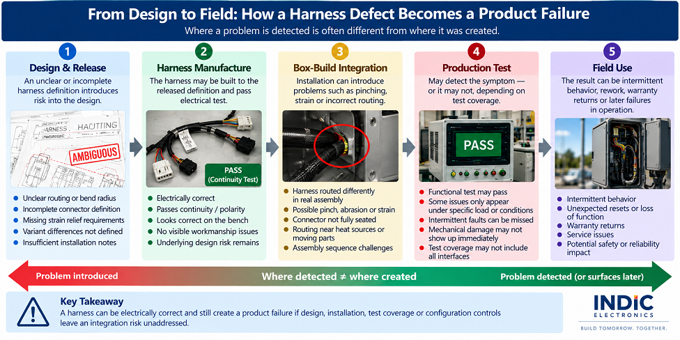
Figure 2. From design to field: how a harness defect becomes a product failure.</strong> A problem may be introduced during design or integration but detected much later. Where a defect is detected is not necessarily where it was created.
Level 3 — System Behavior
The third question is: Does the integrated product function correctly through the harness interfaces?
At this level, the harness is no longer evaluated independently. The product is.
Depending on the system, functional or end-of-line testing may exercise sensors, actuators, motors, interlocks, communications, power paths, controls, user interfaces and configuration-specific functions.
This can expose conditions that standalone harness testing cannot. For example, a connection may show continuity but behave differently when the circuit carries its intended operating load. A communication interface may be correctly pinned but perform poorly because of an implementation problem involving routing, termination, grounding or shielding.
This is why the phrase “100% electrically tested”, by itself, says less than it appears to say.
The useful questions are: What failure modes does the test detect? Under what condition? And what remains outside its coverage?
Different Evidence Answers Different Questions
Potential failure mode
Harness-level electrical test
Installed-state inspection
System / functional test
What may still require separate control
Open conductor
Strong
Limited
Often detectable
Root cause / workmanship
Incorrect pin mapping
Strong when mapping is explicitly tested
Limited
May be detectable
Configuration control
Incorrect routing
No
Strong
Usually indirect
Work instructions / routing control
Connector not fully seated
Limited / depends on architecture
Strong when visible
Often detectable
Assembly process
Harness pinched during enclosure closure
No
Strong
May remain latent
Mechanical design / assembly control
Excessive connector strain
No
Strong
May not fail immediately
Routing / strain relief
Shield / ground implementation problem
Limited
Partial
May expose functional symptom
Design / installation control
Wrong product-variant harness
May pass against wrong test program
Partial
May expose mismatch
Configuration / genealogy
Interface problem under operating load
Usually no
No
Strong if test exercises the condition
Test architecture / requirements
The table illustrates why test coverage must be discussed in terms of failure modes rather than test names. Adding another test station does not automatically close a risk. The test must create an observable signature for the failure being controlled.
Configuration Control Becomes More Important as Product Mix Increases
Complex box builds frequently exist in multiple variants. Those variants may differ in harness branch configuration, connector population, PCBA revision, firmware, sensor configuration, power option, enclosure, or regional or customer configuration.
A harness that is correct for Product Variant A can be completely wrong for Product Variant B while remaining perfectly well manufactured. The resulting problem is not harness workmanship. It is configuration control.
For high-mix production, the release system therefore needs to control not only whether a harness was manufactured correctly, but whether the correct harness revision is being installed into the correct product configuration.
Where product architecture warrants it, genealogy can link harness identity, PCBA revision, product configuration and final-unit serial number. That provides evidence for a different question: What exactly was installed in this unit?
What OEMs Should Release Before the First Controlled Build
A production partner cannot resolve missing product definition through workmanship alone.
For complex assemblies, the OEM release package should define the interfaces sufficiently for manufacturing and NPI teams to determine what constitutes the intended build. Depending on the product, that may include:
harness drawings;
connector and contact specifications;
pin maps;
wire/cable requirements;
branch lengths and dimensions;
labels and identification;
enclosure drawings;
routing constraints;
PCBA I/O definition;
grounding/shielding intent;
mechanical retention requirements;
applicable workmanship/acceptance requirements;
product variants and effectivity;
electrical-test requirements;
system acceptance criteria.
The objective is not paperwork for its own sake. Each controlled artifact should answer a manufacturing question.
What the EMS Should Establish During NPI
NPI converts released product definition into manufacturing evidence.
For harness-integrated products, the NPI process should determine whether:
the released harness can be manufactured consistently;
the harness fits the real mechanical assembly;
the intended routing is practical;
connectors can be mated and inspected;
strain relief and retention work as intended;
the assembly sequence is repeatable;
inspection points remain accessible;
harness-level testing detects the intended manufacturing defects;
system-level testing exercises the interfaces that matter;
revisions and variants can be controlled through production.
The important output of NPI is therefore not simply “The first unit worked.” It is evidence that the manufacturing process can reproduce the intended configuration and that meaningful failure modes have defined controls.
Harness Test and System Test Have Different Jobs
Harness inspection and test primarily provide evidence about the cable/harness assembly.
System functional or end-of-line test provides evidence about selected functions of the completed product.
Neither automatically replaces the other. And neither should be confused with environmental or product qualification.
A production unit passing functional test does not prove long-term durability under every thermal, vibration, humidity, EMC or lifecycle condition. Conversely, a qualified product design does not prove that every production unit was assembled correctly.
The test architecture must therefore be tied to the question being answered.
A Representative NPI Scenario
Consider a control unit containing a PCBA, enclosure-mounted connector and internal harness.
The harness passes its standalone continuity test. The PCBA also passes its board-level test.
During the pilot build, however, technicians find that closing the enclosure pushes one harness branch toward the edge of a metal bracket. The product still passes functional test.
At this point, treating the unit as “passed” would miss the engineering issue.
Level 1: The harness is electrically correct.
Level 2: The installed routing creates an undesirable mechanical interaction.
Level 3: The current system test does not necessarily expose the resulting long-term risk.
The appropriate response is not automatically another electrical test. It may instead require a routing change, additional retention, edge protection, an assembly instruction change or a mechanical-design change, depending on the actual product requirements.
Where Integrated Harness and Box-Build Ownership Can Help
When harness, PCBA, mechanical and test teams can resolve interface problems through the same NPI loop, an issue discovered during box build can be traced back to the responsible engineering artifact: harness drawing, mechanical drawing, assembly process, test definition or configuration data.
That is the real advantage of integration: shorter technical feedback paths across interfaces.
For EV and power-electronics programs, these interfaces can become more demanding because harness routing, high-voltage interlocks, grounding and shielding, enclosure design, electrical test and final system verification may interact. Indic discusses those implementation considerations in its article Wire & Cable Harnessing for PCBA and Box-Build Integration.
That article also documents an EV-charger certification build in which harness cut, termination and labeling were coordinated with box-build activities, while cable-entry points, grommets and strain relief were addressed before potting. Indic reports a ten-unit requirement in five days versus a two-week legacy flow, with a four-day assembly cycle supporting Day-5 delivery. These figures describe that specific published program; they should not be read as a universal cycle-time improvement for harness-integrated builds.
The outcome still depends on the quality of the engineering and manufacturing controls. Simply putting several processes under one roof does not, by itself, establish production readiness.
The Harness Production-Readiness Gate
Before release to repeatable production, the OEM and EMS should be able to answer the following questions.
Harness integrity
Is the correct harness definition released?
Are connector, contact, wire and pin-map requirements controlled?
Are applicable workmanship and acceptance requirements defined?
Does harness-level inspection/test cover the intended manufacturing defects?
Installed integration
Has routing been verified in the production-representative enclosure?
Are bend, strain, clearance and abrasion risks controlled?
Can connectors be reliably mated and inspected?
Is the assembly sequence practical and repeatable?
Are service requirements accommodated where applicable?
System behavior
Does production test exercise the relevant harness-connected functions?
Are load-dependent or configuration-dependent interfaces exercised where required?
Are known gaps in test coverage understood?
Configuration
Are harness and PCBA revisions controlled together where necessary?
Are product variants distinguishable?
Can engineering changes be propagated without creating mismatched configurations?
A “no” does not automatically mean the product cannot proceed. It means the team has identified an unclosed production-readiness question that requires an engineering disposition.
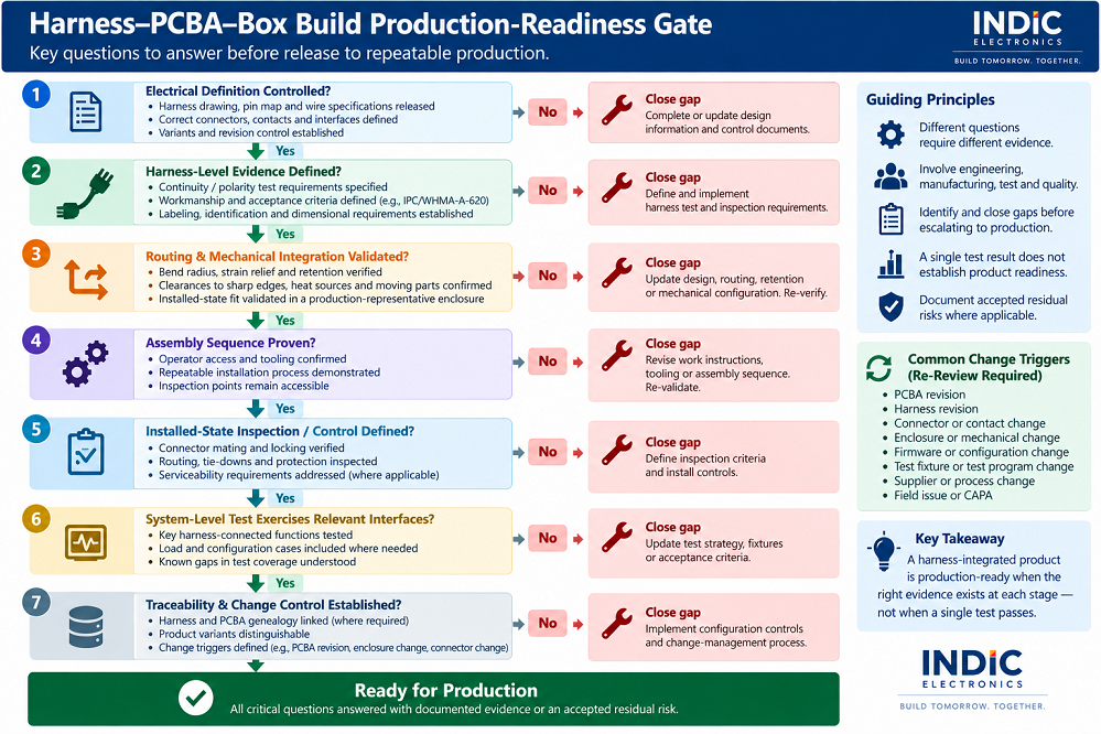
Figure 3. Harness-PCBA-box-build production-readiness gate. Release should consider controlled electrical definition, harness evidence, installed mechanical integration, assembly sequence, inspection, system-level test, and traceability/change control. A gap at any stage should be closed or explicitly dispositioned before repeatable production.
What You Provide; What Indic Helps Close
For an OEM transferring a harness-integrated electronic product, the useful starting information typically includes the released electrical and mechanical definition, connector/pin information, product variants and acceptance requirements.
The manufacturing/NPI task is to convert that definition into a repeatable build process and evidence structure covering harness build → installation → system test → configuration control.
This is where a design-aware EMS/ODM partner can contribute more than assembly capacity: by identifying interface conditions that should be resolved before they become recurring production problems.
Frequently Asked Questions
Is continuity testing enough for a wire harness?
No. Continuity testing can provide strong evidence about electrical connectivity and, depending on the test architecture, opens, shorts or pin mapping. It does not by itself prove correct routing, strain relief, connector installation, mechanical clearance, shielding implementation or behavior of the completed system.
Why can a harness pass electrical test but still cause problems in a box build?
Because the installed harness interacts with the enclosure, connectors and other components. Routing, bend radius, strain, abrasion, connector seating, grounding/shielding and assembly sequence can introduce conditions that do not exist during standalone electrical testing.
When should harness integration be validated?
As early as practical using production-representative PCBA, mechanical and harness configurations, and then during controlled NPI/pilot builds. Waiting until routine production makes interface changes more disruptive because tooling, work instructions, test methods and released documentation may already depend on the existing design.
Does passing functional test prove the harness is reliable in the field?
No. Production functional test verifies selected functions under defined production-test conditions. Long-term environmental, mechanical, EMC and lifecycle performance belong to the appropriate product validation/qualification strategy.
What should an OEM review before releasing a complex harness into production?
At minimum, review the controlled electrical definition, connectors and pin mapping, routing and mechanical constraints, strain relief, assembly sequence, harness-level test, installed-state inspection, system-level test coverage, product variants and change/configuration controls relevant to the product.
Download the PCBA–Harness–Box Build Integration Readiness Worksheet
Use the worksheet to review harness definition, routing and mechanical integration, test evidence, product variants, change triggers and release-gate questions before a complex box build moves into repeatable production.
A harness should not be considered production-ready merely because its drawing has been released and it passes continuity.
For complex PCBA and box builds, the more useful question is whether there is sufficient evidence at three different levels:
Is the harness correct?
Is it correct after installation?
Does the integrated product behave correctly through those interfaces?
Separating those questions makes production-readiness reviews more precise. It also prevents one test result from being asked to prove something it was never designed to prove.
The objective is not to maximize inspection or test. It is to understand the important failure modes, identify where each can enter the product, and establish evidence that supports the appropriate engineering decision before those problems become repetitive production issues.
After signing up the PDF will be emailed to you at the address you provide. Please use a company address - gmail, yahoo, outlook, etc. will not be accepted.
Thank you! Your submission has been received!
Oops! Something went wrong while submitting the form.
Join us to stay updated with our latest blog updates, manufacturing and assembly trends, news and announcements!
Thank you! Your submission has been received!
Oops! Something went wrong while submitting the form.